Inventor design
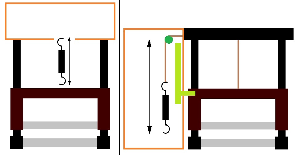
In the picture below you can see (on the left) the original sketch for the mechanical design of the device.
The motor and gear are placed inside the orange box. Also the electronics are fitted in and attached to this box.
However it soon was clear that in this setting there wouldn’t be sufficient room to stretch the spring. Hence we chose to put the orange box on the left of the slider.
The box is much longer in this case, giving enough space to elongate the spring. One end of the spring is connected to the slider, which is in turn connected to the aluminum frame with a kevlar wire, through a system of two pulleys.
The other end is connected via a wire to a pulley on the axis of the worm gear.
Putting the box on the left also offers the advantage that we can integrate potentiometer 1 (light green) in the box.
The slider of the potentiometer is fixed on the brown part (slider) of the device.
The two gray bars in the sketch are grasped by the hand. Because of this it is better to give them a more complicated, ergonomic shape.
In the course “Ontwerpmethodologie” of professor Vanlanduit it is advised to use round shapes for hand grips rather than bars with grooves which match the position of the fingers.
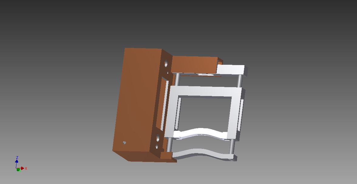
One of the reasons is that these grooved bars are made for an average sized hand, whereas round shapes are more independent of the hand size. The two round pieces are shown in the inventor drawings below.
The white grip is made out of plastic and is made by a 3D printer because the shape is too complicated to be manufactured out of aluminum. It is glued together with the rest of the slider.
The other grip is a bit less complex and therefore made out of aluminum.
Aluminum and plastic frame
The pieces in gray shown in the picture below are made out of aluminum to guarantee sufficient strength of the frame.
The brown piece is partly made out acrylic glass (or PMMA) and partly out of plastic. The acrylic glass forms the 5 sides of the box which contains the electronics, servo, gear, etc.
The board containing the LCD screen, the pushbutton, the LED and the potentiometers was printed out in plastic.
The white 'ergonomic' piece was also printed in plastic because of its complicated shape.
Fitting the components in
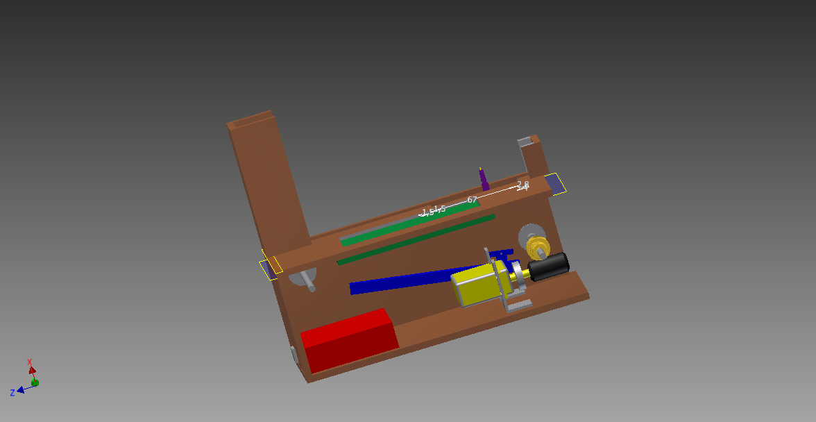
To make sure that everything would fit in the box, we made 3D Inventor drawings of all the pieces.
The result is shown in the picture below. Even though a lot of space is provided fit in all the different pieces,
we still had some of trouble fitting in all the wires going from the Arduino and PCB (in red) to the LCD screen (in green) and other electric components, without interfering with the mechanical components.
In order to more effectively keep the wires and the mechanical components separated, a simple cardboard piece was placed over the spring and potentiometer (not in the drawing).
The spring is stretched between the two axes (in gray). Because the hole of one of the axes was not drilled in the right place, the two axes stood closer together then we originally designed.
This is one of the reasons why the predetermined force level could not be attained.